
Figure No. 205
Operating Pressure Range:
- Semi-steel bodies suitable for 250 PSI steam working pressures.
- Standard flanged or screwed end semi-steel bodies up to 150 PSI steam pressure.
- Extra Heavy flanged or screwed end semi-steel bodies up to 250 PSI steam pressure.
- The No. 205 Regulator is not recommended for reduced pressures lower than 5 PSI or inlet pressures under 25 PSI.
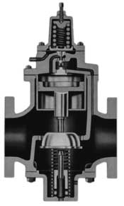
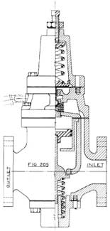
Service: The No. 205 Regulator is a sensitive, internal pilot operated valve suitable for regulating steam, air pressures. It is recommended for high pressure power plant service and performs excellently wherever extreme fluctuations occur in the initial pressure but not permitting variations in the service pressure. Where dead-end service is required the No. 205 Regulator is recommended because, being of single-seat construction, it is “bottle-tight” when closed. Thus the pressure on the service side cannot build up beyond the point for which it is set. The parabolic shaped main disc tends to prevent excessive wire-drawing because, due to design, the steam is deflected beyond the seating area.
Construction Features: The body is constructed of semi-steel and may be ordered with either stainless steel trim. The valve is operated by slight movements of a Metal Diaphragm. Regulators are equipped with high-grade 302 Stainless Steel compression springs calibrated to respond to the slightest variation in pressures. The No. 205 Pilot Valve is self contained with all moveable parts interchangeable and easily replaced without removing the valve from the pipe line. When reduced pressures are exceptionally low for this type of valve, a large diaphragm chamber is used to facilitate and insure accurate regulation.
The pressure on the service side is regulated by one spring. The cylinder is suspended from the top, and the entire design is such as to compensate for the various coefficients of expansion of the different metals. Consequently, the possibility of moving parts sticking and binding due to changes in temperature is eliminated.
Operation: When in service the diaphragm is controlled by the reduced pressure operating against the top loading spring. The auxiliary valve is then actuated and pressure is applied to the piston which has a greater area than the main valve disc. A small variation of the reduced pressure causes the auxiliary valve to open or close in varying degrees. This action is transmitted to the piston and on to the main disc to effect the throttling action necessary to maintain a constant reduced pressure.
When Ordering: Specify valve size, body material and trim, screwed or flanged body and maximum and minimum volume required, if available. State initial and reduced pressures, and if flanged specify drilling.
( With Adjusting Stem )
When conditions exist that make it imperative to install a Figure No. 205 Pilot Regulating Valve larger than is required for present load requirements, the Adjusting Stem unit is a valuable adjunct to the efficiency of operation. As is sometimes the case, a valve is installed to care for future conditions not exisitng at the time of installation. Consequently, by virtue of a minimum load requirement, the Regulator tends to be noisy and objectionable, and lessens efficient control. When such is the case, the Adjusting Stem is strongly recommended.
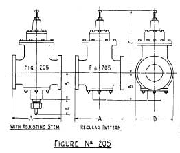
It will be noted that no additional fittings are required for installation. This new feature is designed to fit onto the Bottom Cover of the Regulator as an integral part thereof.
| Roughing – In Dimensions Figure 205 | |||||||
| Size | A- Standard | A- ExHv | B | C | D | E | |
| Screwed | Flanged | Flanged | |||||
| 1 | 7 1/4 | 8 1/4 | 8 1/4 | 4 1/2 | 22 5/8 | 4 3/4 | 2 3/4 |
| 1 1/4 | 7 1/4 | 8 1/4 | 8 1/4 | 4 1/2 | 22 5/8 | 4 3/4 | 2 3/4 |
| 1 1/2 | 7 1/4 | 8 1/4 | 8 1/4 | 4 1/2 | 22 5/8 | 4 3/4 | 2 3/4 |
| 2 | – | 9 15/16 | 10 1/4 | 5 7/8 | 25 | 6 3/8 | 3 3/4 |
| 2 1/2 | – | 10 5/8 | 11 1/8 | 5 7/8 | 25 3/16 | 6 15/16 | 3 3/4 |
| 3 | – | 11 1/4 | 12 | 6 1/4 | 25 5/8 | 8 1/4 | 3 5/8 |
| 3 1/2 | – | 11 1/4 | 12 | 6 1/4 | 25 5/8 | 8 1/4 | 3 5/8 |
| 4 | – | 13 1/16 | 14 | 8 | 29 5/8 | 9 3/4 | 4 3/16 |
| 5 | – | 14 7/16 | 15 7/16 | 9 1/2 | 32 5/8 | 11 13/16 | 4 3/4 |
| 6 | – | 16 7/16 | 17 3/8 | 10 3/4 | 35 3/16 | 13 3/4 | 4 13/16 |
| All Dimensions are in inches | |||||||